Arduino water level controller / indicator.
This article is a about a fully functional water level controller using Arduino. The circuit displays the level of water in the tank and switches the motor ON when the water level goes below a predetermined level. The circuit automatically switches the motor OFF when the tank is full. The water level and other important data are displayed on a 16×2 LCD display. The circuit also monitors the level of water in the sump tank (source tank). If the level in side the sump tank is low, the motor will not be switched ON and this protects the motor from dry running. A beep sound is generated when the level in the sump tank is low or if there is any fault with the sensors.
Circuit diagram.
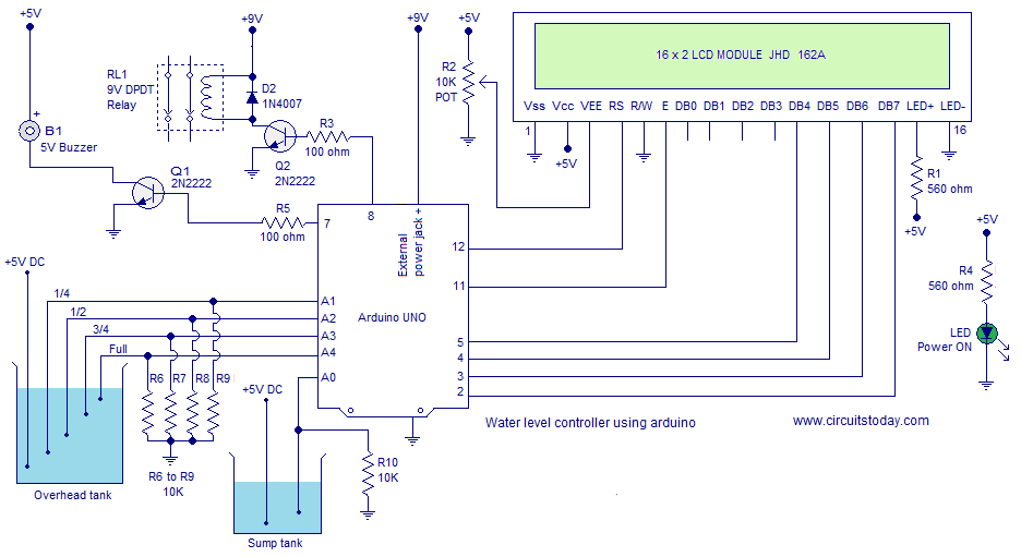
The circuit diagram of the water level controller using Arduino is shown above. Conductive method is used to measure the level. The sensor assembly consists of four aluminum wires arranged at 1/4, 1/2, 3/4 and full levels in the tank. The dry ends of these wires are connected to analog input pins A1, A2, A3 and A4 of the Arduino respectively. A fifth wire is positioned at the bottom of the tank. Resistors R6 to R9 are pull down resistors.The dry end of this wire is connected to +5V DC. When the water touches a particular probe, electrical connection is established between that probe and the +5V probe because water has slight conductivity. As a result current flows through that probe and this current is converted into a proportional voltage by the pull down resistor. Arduino reads the voltage dropped across each pull down resistor for sensing the level of water in the tank. Same method is used for measuring the level of water in the sump tank.
Digital pin 7 of the Arduino controls the buzzer and digital pin 8 controls the motor. Transistor Q1 drives the buzzer and resistor R5 limits the base current of Q1. Transistor Q2 drives the relay. Resistor R3 limits the base current of Q2. D2 is a freewheeling diode. POT R2 is used to adjust the contrast of the LCD. resistor R1 limits the current through the back light LED. Resistor R4 limits the current through the power ON LED. Complete program for the water level controller using Arduino is given below.
Program.
#include <LiquidCrystal.h>
int sump=A0;
int qut=A1;
int hlf=A2;
int thf=A3;
int ful=A4;
int motor=8;
int buz=7;
int s;
int q;
int h;
int t;
int f;
int i;     //motor status flag
int v=100; //comparison variable(needs some adjustment)
int b=0;   //buzzer flag
int m=0;   //motor flag
int c=0;   //sump flag

LiquidCrystal lcd(12, 11, 5, 4, 3, 2);

void setup()
{

pinMode(qut,INPUT);
pinMode(hlf,INPUT);
pinMode(qut,INPUT);
pinMode(ful,INPUT);
pinMode(sump,INPUT);
pinMode(motor,OUTPUT);
pinMode(buz,OUTPUT);
lcd.begin(16, 2);
digitalWrite(buz,LOW);
}

void loop()
{

i=digitalRead(motor);
s=analogRead(sump);
q=analogRead(qut);
h=analogRead(hlf);
t=analogRead(thf);
f=analogRead(ful);
lcd.clear();

if(f>v && t>v && h>v && q>v )
{
lcd.setCursor(0,0);
lcd.print(char(219));
lcd.print(char(219));
lcd.print(char(219));
lcd.print(char(219));
lcd.setCursor(5,0);
lcd.print("FULL");
m=0;
b=0;
}
else
{
if(f<v && t>v && h>v && q>v)
{
lcd.setCursor(0,0);
lcd.print(char(219));
lcd.print(char(219));
lcd.print(char(219));
lcd.print("_");
lcd.setCursor(5,0);
lcd.print("3/4th");
b=0;
}
else
{
if(f<v && t<v && h>v && q>v)
{
lcd.setCursor(0,0);
lcd.print(char(219));
lcd.print(char(219));
lcd.print("_");
lcd.print("_");
lcd.setCursor(5,0);
lcd.print("HALF");
m=1;
b=0;
}
else
if(f<v && t<v && h<v && q>v)
{
lcd.setCursor(0,0);
lcd.print(char(219));
lcd.print("_");
lcd.print("_");
lcd.print("_");
lcd.setCursor(5,0);
lcd.print("1/4th");
b=0;
}
else
{
if(f<v && t<v && h<v && q<v)
{
lcd.setCursor(0,0);
lcd.print("_");
lcd.print("_");
lcd.print("_");
lcd.print("_");
lcd.setCursor(5,0);
lcd.print("LOW");
b=0;
}
else

{
digitalWrite(motor,LOW);
lcd.setCursor(0,0);
lcd.print("ERROR!");
b=1;
}
}}}
if(i==HIGH)
{
lcd.setCursor(0,1);
lcd.print("Motor ON");
}
else
{
lcd.setCursor(0,1);
lcd.print("Motor OFF");
}


if(s>v && m==1)
{
digitalWrite(motor,HIGH);
}
if(s<v)
{
digitalWrite(motor,LOW);
lcd.setCursor(11,0);
lcd.print("Low");
lcd.setCursor(11,1);
lcd.print("Sump");
c=1;
}
if(s>v)
{
c=0;
}

if(m==0)
{
digitalWrite(motor,LOW);
}

if(b==1 || c==1)
{
digitalWrite(buz,HIGH);
delay(500);
digitalWrite(buz,LOW);
}
else
{
digitalWrite(buz,LOW);
}
delay(100);
lcd.clear();
}
About the program.
The Arduino reads the sensor output through the analog input pins using analogRead function. For example q=analogRead(qut); converts the voltage (in the range 0 to 5V) at the “quarter” probe into a number (in the range 0 to 1023) and saves it into the variable “q”. This way the voltage at each prob is scanned to corresponding variables. The these variables are compared to a fixed number (100 here) for identifying the current condition. Actually 100 is the equivalent of 0.48 volts and if the voltage at a particular sensor is greater than this, it is considered as an electrical continuity and water is assumed to be touching the probe. The vale of the fixed number (comparison variable”v”) needs some adjustment because the resistivity of water changes from place to place and the gap between the sensor probes will be different in different tanks.
Notes.
- The circuit is powered through the 9V external power jack on the arduino board.
- 5V needed at different points in the circuit can be tapped from the 5V output on the arduino board.
- Use good quality aluminum wires for probe. Do not use copper wires.